

Testing
Summary
For the testing of this device, the main objective will be to ensure smooth operation, durability and ability to maneuver and move quickly and easily. Examples of mandatory tests include testing for a top speed of at least 20mph, front wheels having the ability to turn 60 degrees both left and right and the car being able have enough torque to overcome the inertia of the geartrain.
These tests pertain to crucial aspects of the car, with an example being the speed test, where the car will be tested to see whether it can go at the max speed goal of 20mph on flat, smooth terrain that must be at least 30 feet long for testing purposes. The turning angle of the car will also be tested, with the goal being a 60-degree turning angle both left and right for each front wheel. Depending on the impact of friction on car turning, this test may also be performed in different environments to gather data in different terrains. The final test for the drivetrain and steering will be an inertia test, where inertia calculations will be shown and compared to the inertia of the drivetrain before, showing the improvement of the system. The goal for this test will be for the car to simply drive forward, which will show contrast with the previous design that simply did not work, proving that the redesign of the car fixed the issue, and that inertia was the true problem with the initial design.
All data for all three tests will be recorded in Excel spreadsheets, with equations set in place to calculate required variables from raw data. For example, the speed test will involve recording total distance travelled and time and will calculate velocity from these values. Video recordings of trials will be recorded as well, mostly for the purpose of finding this data. For the turning test, video will not be needed, but images may be taken to prove the validity of the test and to analyze for problems to troubleshoot in the system.
There were no major testing changes to the top speed test throughout spring quarter, due to the test having a straightforward goal that was known since fall quarter. The inertia test was only just designed in spring quarter, and since the design has had no adjustments. This is due to the test being focused on mathematics, with the test being simply if the car can drive. The steering angle test remained mostly the same but was slightly modified to add an extra precaution that was needed for smooth vehicle operation. A question that arose before testing began was whether the car would be able to turn quickly. This was addressed by adding the steering time to the measurements, to assure that the car could quickly turn. This change was deemed unnecessary after it was realized that the assembly could turn within half a second, but the change was still a good step to take. For deliverables, the plan has had no adjustment.
Process
Figure 1 demonstrates part of the Steering Time and Angle test procedure, which is the first test conducted on the RC Baja car. This step involves the wheel being turned to the maximum possible angle, which was marked with a pen and measured to determine angle. The design failed this test.
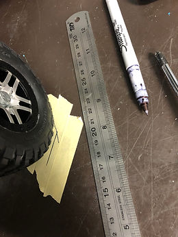
Figure 1
Figure 2 contains the mathematics done to ensure the functionality of the drivetrain after the redesign. The calculations consisted of the use of givens such as outer/inner radii and weight to determine inertia for all rotating components. These were added up and used to determine the torque.
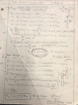
Figure 2
Figure 3 is a video of the assembly in motion in the same way that the maximum speed test was conducted. This test measured the maximum speed of the assembly, with the ideal speed being 20mph. The maximum recorded speed was only 14mph, so this test was a failure.
Figure 3
Figure 4 contains a video of the car in motion while confirming the results of the inertia/torque test because it is able to move, this test is successful.
Figure 4
Figure 5 contains a picture of the battery fastening system. The requirement was that it must be removed in no more than 5 minutes, and so velcro was used to easily meet this requirement.

Figure 5
Figure 6 depicts the testing process of the steering. The max turning position would be recorded straight with a ruler before being measured with a protractor for angle.
Figure 6
Figure 7 depicts the testing of the finished assembly being able to fit completely within the span of the wheels. This requirement is important to ensure that the drivetrain does not get damaged in the event of a collision. This image from above clearly shows that this design concept was implemented successfully.

Figure 7
Figure 8 depicts the old iteration of the device. In the inertia/torque test, it was discovered that this design required 1.8N of torque to turn, where the motor old put out 0.15N of torque. This resulted in the car being unable to accelerate, requiring a total overhaul.

Figure 8