Analysis
Analysis Summary
-Analysis 1 involves calculating RPM and power output of the motor.
-Analysis 2 calculated the net transmission gear ratio between the motor gear and ring gear.
-Analysis 3 calculated the optimal radius for the driveshaft.
-Analysis 4 calculated the maximum shear force that will be experienced by components.
-Analysis 5 improved upon the result of Analysis 3, finding a driveshaft radius that can also withstand the drop test without breaking.
-Analysis 6 determined an optimal diameter for the rear axles based on the drop test and the torque from the motor.
-Analysis 7 determined specs for the two transmission gears.
-Analysis 8 determined specs for the differential pinion and ring gear, and the revised net gear ratio.
-Analysis 9 calculated the required pin diameter for the tie rod pin to withstand torque from the servo.
-Analysis 10 approximated the optimal tie rod length.
-Analysis 11 analyzed and determined a suitable candidate for the miter gears.
-Analysis 12 determines steering mechanics.
Analysis Requirements
The primary requirements for these analysis are that they allow for the design of a functional, competitive RC Car. The analyses below should broadly cover all major design parameters that have the potential to lead to failure in the assembly, and should ensure through application of engineering methods that all parts are successful.
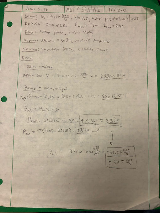
Analysis 1
This analysis finds two essential parameters for future analysis of the car. One is torque produced by the motor, which will be important in ensuring prolonged endurance of axles and gears through stress analysis, and the other is RPM, which will be used to determine gear sizing and ratios for going at 25mph. The mathematics needed for this analysis consisted of the calculation of motor power for finding torque, and the usage of voltage and Kv rating to calculate RPM. The torque produced by the motor will dictate the size of the drive gear and driveshaft, and the RPM is required for the calculation of gear ratios, which are important for the construction of the differential.
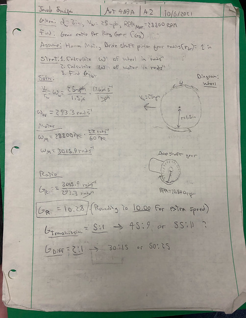
Analysis 2
This analysis fulfills the requirement of the car to have a specific gear reduction in order to reach a maximum speed of 25mph. The analysis that took place to calculate the gear reduction involved calculating angular velocities of both the drive shaft gear and the wheel. There are no physical design parameters associated with this value, but it will dictate the gear ratio between the driveshaft gear and the ring gear. This parameter will be documented on the ring gear drawing, as it is a requirement of its design.
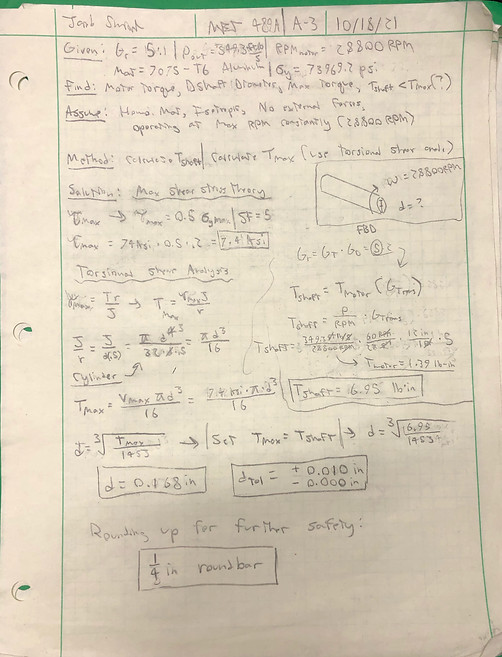
Analysis 3
This analysis determines the optimal radius of the driveshaft by calculating and analyzing the torque in order to ensure that the axles can survive the torsional shear stress caused by the motor, assuming that the car is in constant motion at 25mph. The analysis required the previously calculated RPM and power output from the motor, and included the calculation of motor torque, driveshaft torque, torsional shear, and maximum allowable torque with the given material, Aluminum Alloy 7075-t6. The physical design parameter associated with the results of this analysis is the diameter of the driveshaft. The design parameter is noted on drawing 20-002 as the width of the driveshaft.
Analysis 4
This analysis (App. A-4) determines the minimum shear force that all components must be able to withstand by calculating the average force on each component during the drop test. The analysis is performed using a combination of conservation of energy principles, simple kinematics and work calculations. The parameter that will be generated from this analysis will be a shear force value in pounds which will act as a lower bound for what shear components must be able to withstand. While this analysis will not generate a value that will be directly observed in part drawings, it will be used to confirm safety of potential designs for every part that is vulnerable to damage from a force exerted by the drop test.
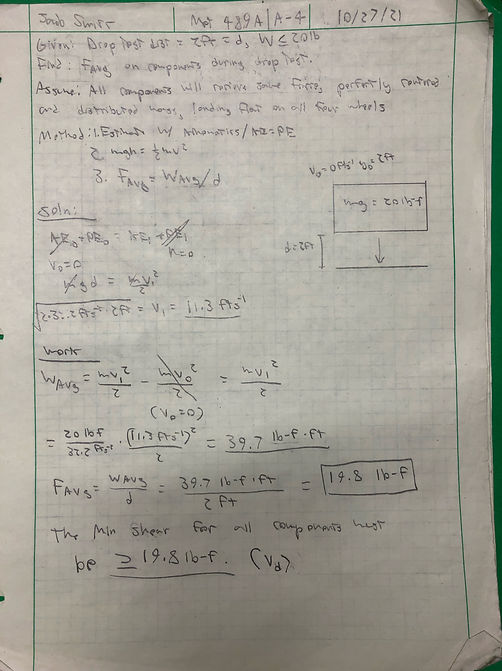
Analysis 5
This analysis (App. A-5) aims to adjust the radius of the driveshaft in order to allow it to reliably survive the force exerted by a drop test from 2ft, as was calculated to be 19.8lbf in App. A-4. This is required so the car can stay operational after a drop test. The analysis required the aforementioned force value, the previously calculated diameter of the shaft, as well as the maximum tolerable shear stress given the material of 7075 t6 aluminum. The analysis involved the calculation of maximum bending stress based on a point force, and the estimated point force was placed in the middle of the beam to provide a high-end estimate. This analysis concluded that the driveshaft could only withstand 21lb of vertical force, which approximates to SF=1 for r=.25in. This is too low of a SF due to the 19.8lbf benchmark being a rough estimate, so another common size, r=5/16in was tried and produced SF = 2.5, which is satisfactory for this part. This value will be documented in drawing JRS_20-002, as this analysis describes the diameter for this part.

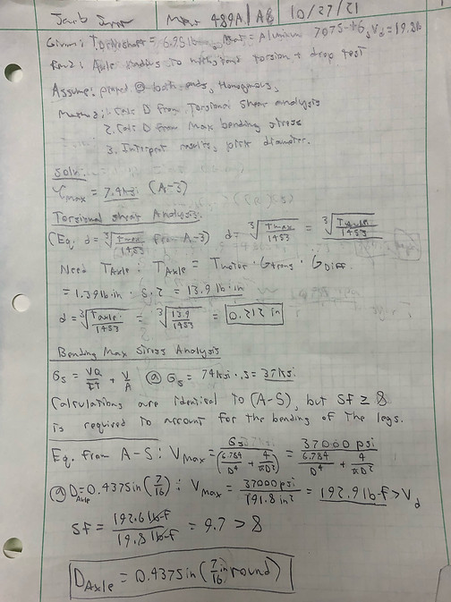
Analysis 6
This analysis (App. A-6) determines the optimal radius of the wheel axles using both maximum shear due to impact and maximum torsional shear stress analysis. The analysis required was similar to the combined procedure of analysis 5 and 3, with the larger of the two radii being selected to ensure safety and part longevity. A heightened safety factor was used to ensure that any compressive forces related to the movement of the legs attached to the wheels do not cause fracture in the axles. This design parameter will be documented in drawing JRS_20-004 as the diameter.
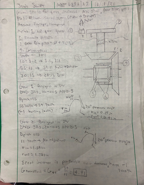
Analysis 7
This analysis (App. A-7) determines the number of teeth in each transmission gear, the pressure angle and the real gear ratio. It will also include a radius for the gears that will be generated from the known specs. This analysis fulfills the requirement of having gears that reduce the motor RPM with an adequate gear ratio of 5:1 while properly meshing in a way that allows for long part life. The analysis done for this step included research into common pressure angle and teeth numbers for small gears, the calculation of the number of teeth, and using SolidWorks analysis to calculate the inner and outer radii. Finally, the final gear ratio was calculated with the adjusted gear ratios. Hunting teeth were removed from the gear in both instances, as the top speed will likely not exceed 25mph anyways due to friction, which was not accounted for in earlier calculations. The values from this analysis are observed in drawings JRS_20-003 and JRS_20-005, which are the motor gear and transmission gear, respectively. The only problem that needs adjustment with this analysis is the fact that SolidWorks did not provide nice numbers, with the outer radii for the parts being 1.781in and 0.41in. Compromises will need to be made to find suitable purchasable parts that fit the requirements.
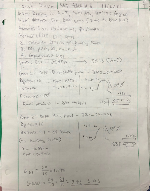
Analysis 8
This analysis (App. A-8) determines the number of teeth in each gear, the pressure angle and the gear ratio in the differential gears. It will also have a radius calculated by SolidWorks. This analysis will be almost identical to A-7, but will be considering the main differential gears instead of the transmission gears. The ratio must be 2:1 (not including hunter teeth) to satisfy the requirements. The analysis that was performed is the same as A-7, it included researching industry standards for gear specs and using them to find an adequate radius for the gears needed in this design. The calculated parameters include the radius, pitch diameter and number of teeth in all gears, as well as a physical design to base purchases off of. These parameters will be documented in drawings JRS_20-006 and JRS_20-008, as the radii of the differential gears.
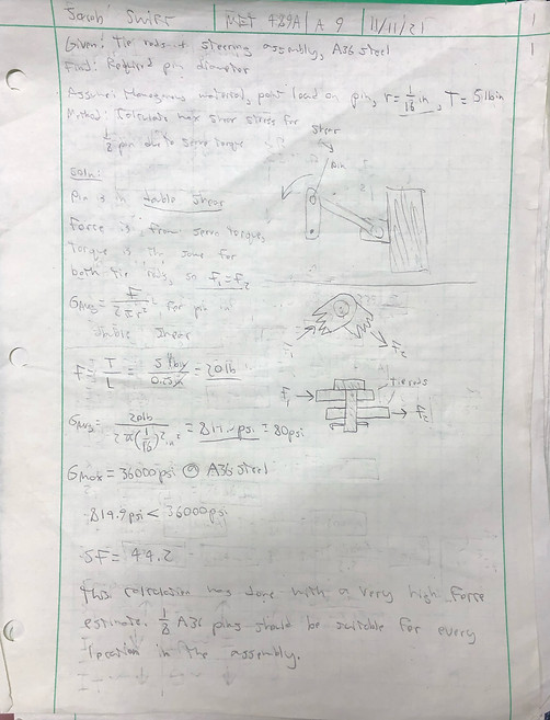
Analysis 9
This analysis (App. A-9) determines the required pin diameter to withstand double shear from both tie rods during the process of turning the wheels. The requirement that is fulfilled by this analysis is ensuring that the steering servo can effectively transfer power to both tie rods in order to turn the wheels, enabling better maneuverability. This analysis will be an analysis of a body that is in double shear, and will require a double shear stress analysis. The pin diameter of 1/8in will be tested first, and the stress that the shear forces cause on this pin will be compared to the maximum stress for the material, A36 steel. If the safety factor is greater than or equal to 8, the 1/8in value will be accepted for the pin diameter and will be the calculated value for the assembly. This value will be documented on drawing JRS_20-007, the drawing of the pin.
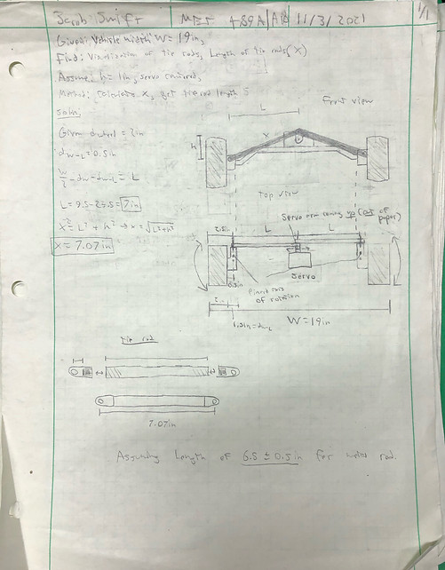
Analysis 10
This analysis (App. A-10) produces a better visualization and a length value for the tie rod. This analysis required basic triangular geometry to solve, as well as study of other similar systems. Based on the common diameters seen in rc car tie rods, a diameter of 1/4in will be used for the design of the tie rod. The distance between the servo, which is assumed to be perfectly centered in the car, was measured against the vertical distance between the end of the upright servo arm and the pinned locations near the wheels. This was used to calculate the approximate value of the length. This length was reduced due to the length that connectors add to the rod, and the final length was projected to be around 6.5in. The drawing will be made at 7in, as if the tie rod is too long it can be machined to be the correct length. This parameter will be located in the drawing of the tie rod shaft, drawing no. JRS_20-008.
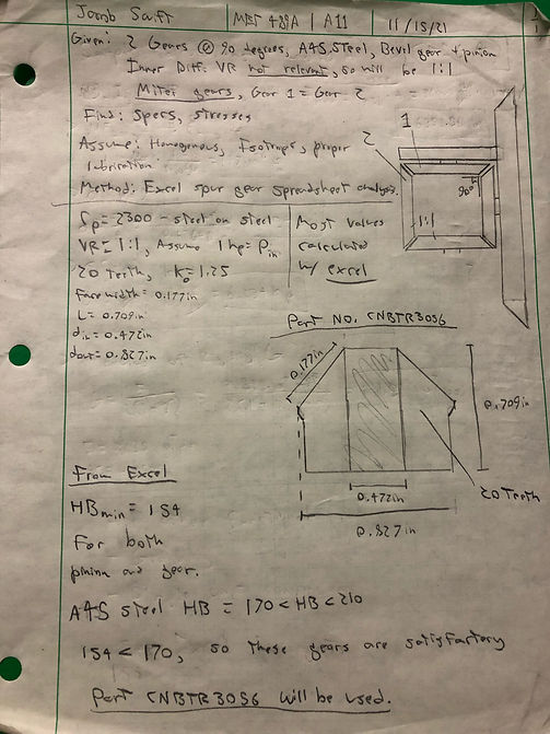
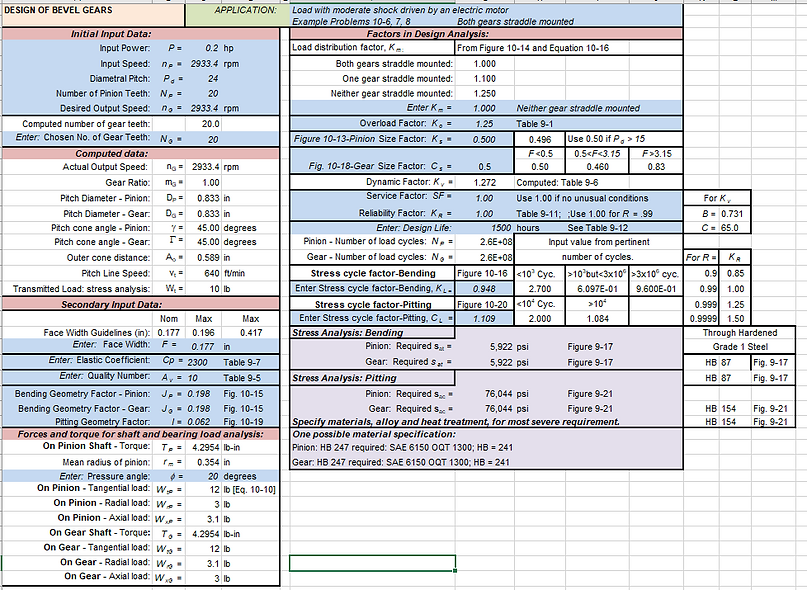
Analysis 11
This analysis (App. A-11) analyzes the inner differential miter gears and determines their properties, then matches these requirements up to a real purchasable item. Using physical properties of a purchasable gear located on amazon.com, part no. CNBTR3056, the requirement of having a sturdy pair of miter gears that could transfer up to ½ the total differential rpm without breaking was fulfilled in accordance with the spur gear/pinion design spreadsheet, a screenshot of which is included in the analysis. The analysis here was performed almost entirely in the spreadsheet, with values either being calculated, assumed or given due to the known specs of the gear, and the spreadsheet generating a required hardness value for the gear material of 154HB. Gear CNBTR3056 satisfied all requirements, being composed of A45 Steel with a minimum 170HB. Parameters calculated from this analysis were numerous, and included face width, pitch diameter, diametric pitch, number of teeth, total length and width, and hole diameter. The specs and dimensions of this gear were modeled in SolidWorks, and this gear and all associated parameters are located in drawing JRS_55-001.
.jpeg)
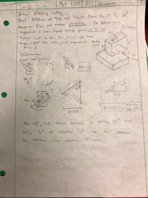
Analysis 12
This analysis (App. A-12) analyzes the distance that the tie rod anchor must be from the axis of rotation of the steering mechanism to ensure that a 60 degree turn angle can be achieved. This is done to fulfill the requirement of being able to turn 60 degrees in either direction with each wheel. This analysis was not heavily based in engineering principles, and was more of a geometrical analysis that involved the relationships between triangle dimensions. The primary design parameter that this analysis determined was the distance between the anchorage point of the tie rod on the wheel pivot and the pinned axis of rotation that is needed to enable the wheels to turn 60 degrees with a servo angle change of 30 degrees from vertical. Both team members will work together on these pivots, as it concerns both the chassis design and the steering design, and the report that will cover the part will most likely be on the Chassis and suspension report by Sean Gordon. This parameter will be documented in the design of the frontal A-Arm pivots.